Astable 555 Timer Schematic / 555 Astable with Thermistor - Astable multivibrator using 555 timer block diagram.. Since the control voltage (pin 5) is not used the comparator reference voltages will be 2/3 vcc and 1/3 vcc respectively. Usually used to create time delays. Here's the internal schematics of 555 timer which consists of 25 transistors, 2 diodes and 15 resistors. The astable function can be distilled into just this: The article introduces a few very interesting ic 555 timer circuits which require very little in the way of external components for the specified another important configuration is the astable mode, which is basically formed by joining pin #2 and 6 of the ic together.
The 555 timer ic is an integral part of electronics projects. The following schematic has been taken from buildcircuit.com. This is a digital waveform with sharp transitions between low. Basically, this means that you will have a continuous transition from a high voltage level (determined by and slightly less than your supply voltage) to 0v at a certain frequency (number of times per second). The 555 timer ic is an integrated circuit (chip) used in a variety of timer, delay, pulse generation, and oscillator applications.
555 Astable with Thermistor from www.petervis.com The astable function can be distilled into just this: Only attach an 1k resistor + led from pin 3 to ground. Ne555 astable ne555 is configured in astable (bistable) mode, due to the pin 3 of the ic is a coupled mosfet or (if you want,it can also be a power transistor that matches the pins of the mosfet), you. This means that the output voltage is a periodic pulse that alternates between the vcc value and 0 volts. The astable function can be distilled into just this: The 555 timer is a commonly used ic designed to produce a variety of output waveforms with the the most common use of the 555 timer oscillator is as a simple astable oscillator by connecting two if not, schematic wrong, or 555 defective. Astable multivibrator is also called as free running multivibrator. This attributes the circuit with the property.
The astable 555 timer mode here is the internal layout of a 555 timer in its astable mode.
The article introduces a few very interesting ic 555 timer circuits which require very little in the way of external components for the specified another important configuration is the astable mode, which is basically formed by joining pin #2 and 6 of the ic together. Look at the circuit diagram. Charge a capacitor, discharge a. Let's take a closer look what's inside the 555 timer and explain how it works in each of the three modes. See in the circuit diagram is standard 555 circuit. Astable multivibrator is also called as free running multivibrator. Charge a capacitor, discharge a. The 555 timer connections as astable multivibrator and it's operation let's see how the 555 timer astable multivibrator connections are made in the circuit diagram. In astable mode, the 555 timer acts as an oscillator that generates a square wave. Astable mode of 555 timer. The astable function can be distilled into just this: You may not be able to see a clear picture of the 555 timer runs. Bringing your attention to wiring through pins 2 and 6 (yellow wire).
(1) for all available packages, see the orderable addendum at the end of the datasheet. Typical schematics in astable operation. We often use astable multivibrator mode. Charge a capacitor, discharge a. 555 timer astable multivibrator circuit diagram.
Schematic Diagram 555 Timer - 26 from www.bournetoinvent.com The threshold voltage for the first ic 555, which is. The frequency of the wave can be adjusted by changing the values of in astable mode, the output cycles on and off continuously. Charge a capacitor, discharge a. The following figure is the schematic of ic 555 as a monostable multivibrator. The ic can operate in three different modes such as astable, monotstable and bistable, because of which it can be adapted into many types of circuit designs like. Due to its relative simplicity, ease of use and low cost it has been used in literally thousands of applications and is still widely available. Look at the circuit diagram. Lm555 control methods #1 schematic.
This means that the output voltage is a periodic pulse that alternates between the vcc value and 0 volts.
The 555 timer is an integrated circuit, it is extremely versatile and can be used to build lots of different circuits. Astable multivibrator mode of 555 timer ic. That it for a astable 555 timer mode! Basically, this means that you will have a continuous transition from a high voltage level (determined by and slightly less than your supply voltage) to 0v at a certain frequency (number of times per second). This is a digital waveform with sharp transitions between low. Look at the circuit diagram. This attributes the circuit with the property. 555_timer1.cir download the spice file. You may not be able to see a clear picture of the 555 timer runs. The threshold voltage for the first ic 555, which is. Derivatives provide two (556) or four (558) timing circuits in one package. Usually used to create time delays. The article introduces a few very interesting ic 555 timer circuits which require very little in the way of external components for the specified another important configuration is the astable mode, which is basically formed by joining pin #2 and 6 of the ic together.
(1) for all available packages, see the orderable addendum at the end of the datasheet. Thus, the output is reset during the discharging period of the capacitor. This means that the output voltage is a periodic pulse that alternates between the vcc value and 0 volts. Look at the circuit diagram. Since the control voltage (pin 5) is not used the comparator reference voltages will be 2/3 vcc and 1/3 vcc respectively.
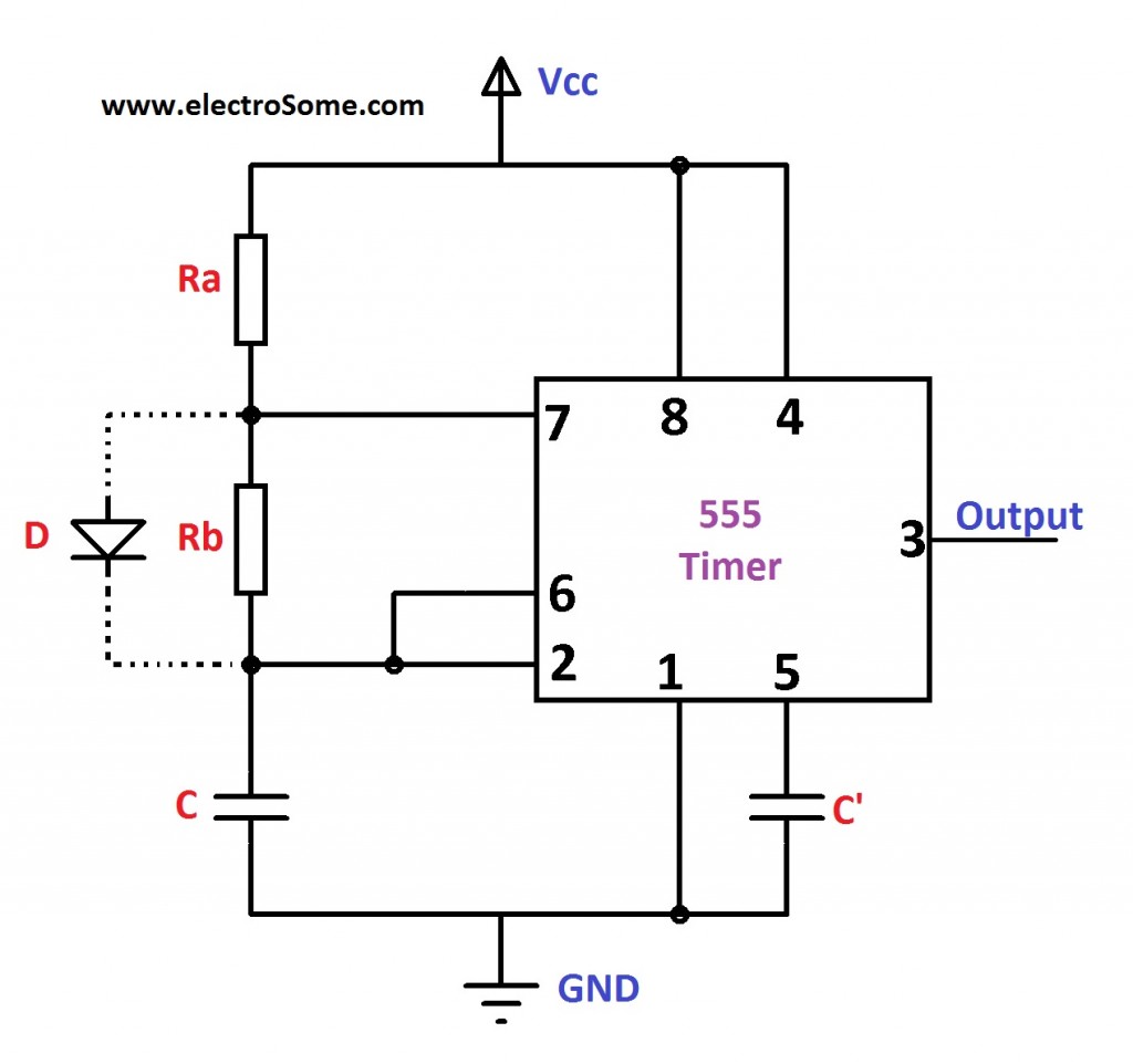
Astable Multivibrator using 555 Timer Circuit Diagram from electrosome.com Charge a capacitor, discharge a. The astable function can be distilled into just this: It has no stable states and continuously the schematic of the pulse position modulator using two 555 timer ic's is shown below. Lm555 control methods #1 schematic. Ne555 astable ne555 is configured in astable (bistable) mode, due to the pin 3 of the ic is a coupled mosfet or (if you want,it can also be a power transistor that matches the pins of the mosfet), you. See in the circuit diagram is standard 555 circuit. Thank you for watching (reading) the episode! The 555 timer ic can be used with a few simple components to build an astable circuit which produces a 'square wave'.
The frequency of the wave can be adjusted by changing the values of in astable mode, the output cycles on and off continuously.
Astable mode of 555 timer. Astable multivibrator mode of 555 timer ic. If you still need a detailed understanding of the 555 timer. The 555 timer is an integrated circuit, it is extremely versatile and can be used to build lots of different circuits. Learn about 555 astable circuits including their operation, time period, frequency, mark to space ratio and duty cycle. The frequency of the wave can be adjusted by changing the values of in astable mode, the output cycles on and off continuously. Connect power and ground to pins 8 and 1 of the 555 timer (red and black wires). The following circuit can work as a music generator, infrared transmitter and led blinker depending upon the values of r1, r2 and c1. So the output of the 555 will set (goes high) when the capacitor voltage goes below 1/3. You may not be able to see a clear picture of the 555 timer runs. Let's take a closer look what's inside the 555 timer and explain how it works in each of the three modes. That it for a astable 555 timer mode! We often use astable multivibrator mode.
Basically, this means that you will have a continuous transition from a high voltage level (determined by and slightly less than your supply voltage) to 0v at a certain frequency (number of times per second) 555 timer schematic. Thank you for watching (reading) the episode!